Three independent circuits
Storage, monitoring and delivery work as one system.
Each tank supplies its own product line. The pump, containment, monitoring and dispenser connect along that circuit.
Discuss a station projectYour station, piece by piece
Identify each piece of equipment and review the options available for a quote.
A one-minute walkthrough
Follow the product path from underground storage to the nozzle.
Start when you are ready. The tour never starts by itself.
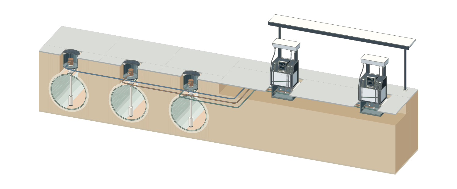
Conceptual schematic for exploring components. Verify the configuration for each project.
Three independent circuits
Each tank supplies its own product line. The pump, containment, monitoring and dispenser connect along that circuit.
Discuss a station projectUnderground storage
The pump, fill, gauging probe and vent use separate connections. A tank sump and sealed entry boots contain and protect penetrations.
Ask about tank systemsTank assembly
The fill connection, submersible pump, monitoring probe and vent each have a dedicated path. Their layout here is conceptual.
OPW mechanical entry boot OPW vent valveSubmersible pump
The head and manifold sit inside the tank sump. A column tube descends to the submerged motor-pump near the tank bottom.
Ask about pumping systemsMotor-pump unit
The motor and pump operate as one selected unit below the column tube. This conceptual cutaway does not identify a power rating or model.
Review pumping requirementsFilling
Fuel enters through the fill adapter and descends through a drop tube. The fill spill container is separate from the pump sump.
A remote delivery point uses a lateral line to reach its own tank-top fill sump and drop tube. Route, slope and protection require project design.
Tank gauging
The probe measures the tank through its own access and cable route. A separate sensor can monitor liquid in the sump. Probe configurations may include a product float; a lower water float is optional and depends on the selected probe.
Ask about tank monitoringSecondary containment
The tank sump surrounds the pump head. Boots seal the product, power and monitoring routes through its wall; the sump sensor reports to monitoring.
Explore OPW entry bootsPower and signals
The flexible conduit reaches the pump connection box. The sump sensor uses its own signal route and sealed entry. The drawing explains their location; cable types and connections depend on the selected equipment.
Tank venting
The tank connection, entry boot, vent pipe, supports and terminal form a separate assembly. This is not the fuel supply line or an equipment cooling fan. The terminal is conceptual; its model and pressure/vacuum setting require selection for the project.
Product distribution
Each product follows its own route from the pump to the dispenser. The colored paths aid reading and are not a regulatory code or an installation layout.
Review project requirementsDispensing equipment
The conceptual cutaway references the Wayne Helix family. The exact number of products, filters, meters and connections depends on the selected configuration.
Explore the Wayne Helix familyCabinet
The display and controls serve the user. Filtration, metering and product control sit in the hydraulic section; exact layouts vary by configuration.
Explore Wayne HelixShear valve
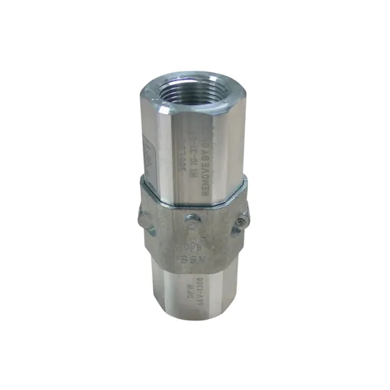
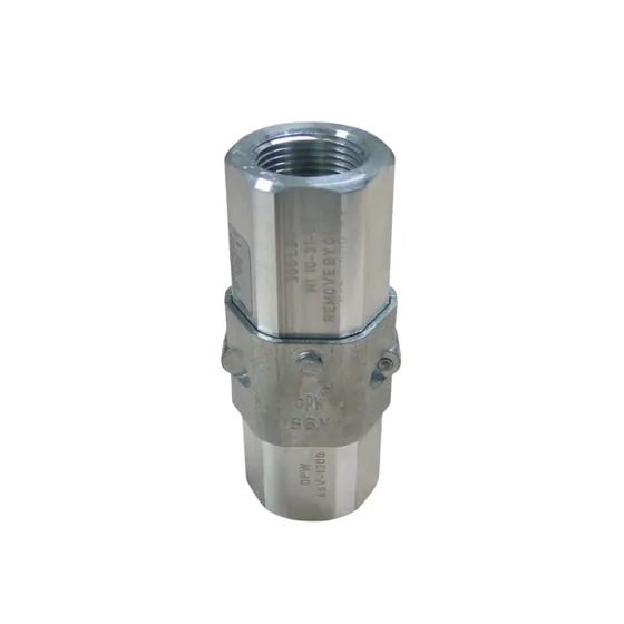
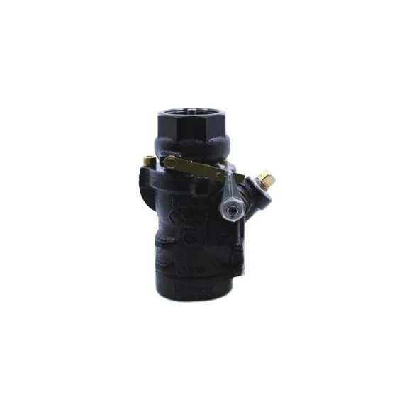
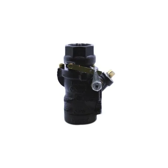
The shear valve is secured at the dispenser base, with its shear section at island level. It is distinct from the hose breakaway; the sump wall is not structural anchorage.
OPW shear valveFiltration
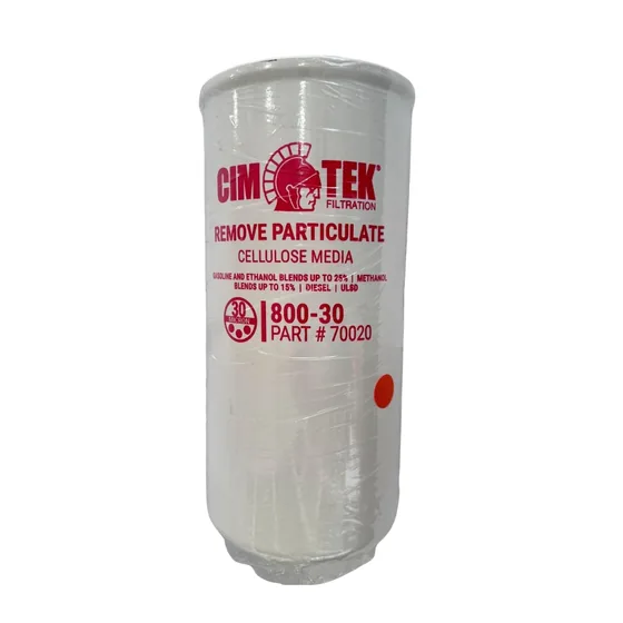
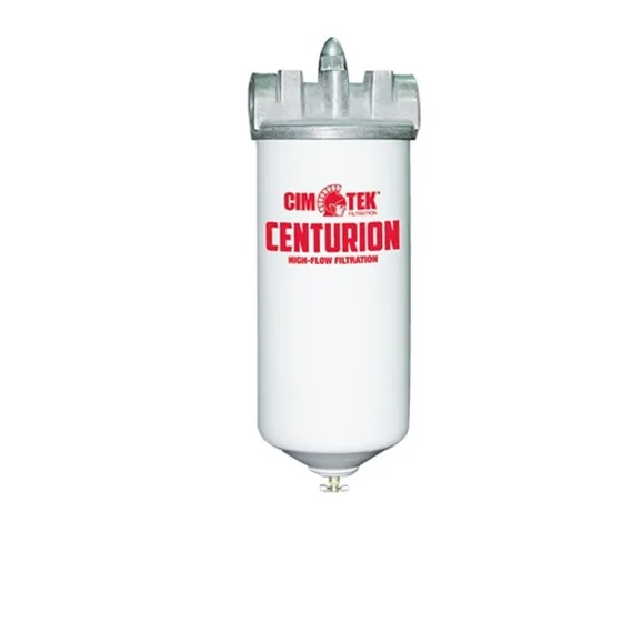
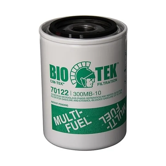
Product enters and leaves through the filter head. Thread, media, fuel and equipment must be checked before selecting a replacement.
Explore catalog filtersDelivery path
Outlet → short hose → breakaway → main hose → swivel → nozzle. Product, lengths and connections must be checked for each equipment configuration; this diagram is not a preselected kit.
Nozzle · OPW 11AP reference
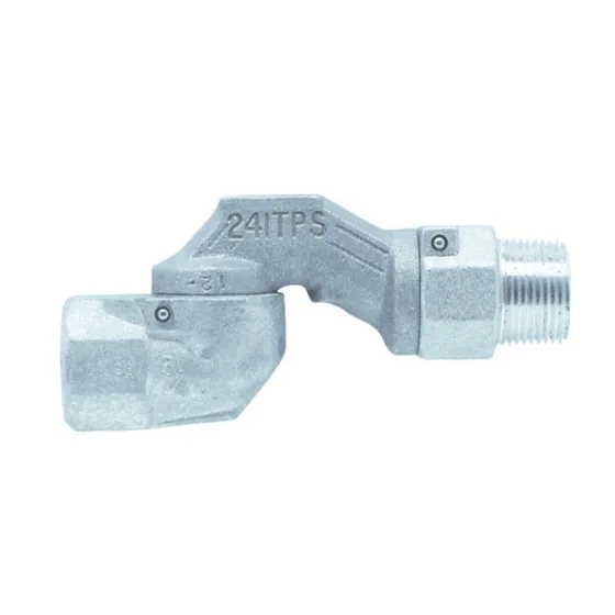
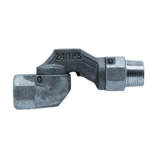
Swivel · OPW 241TPS reference
Main dispensing hose
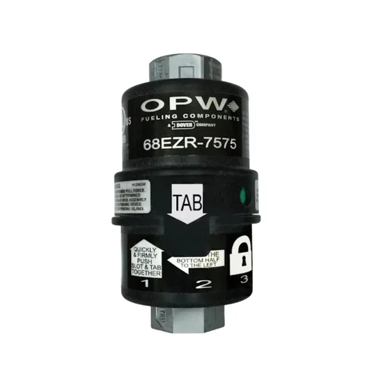
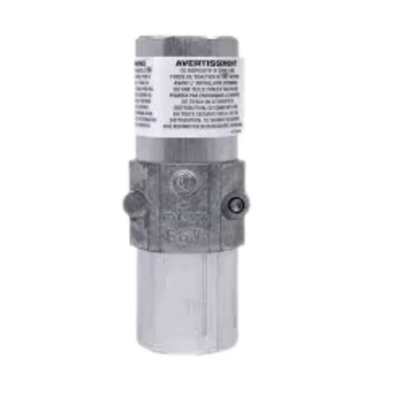
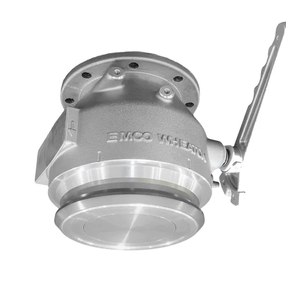
Breakaway · OPW 68EZR reference
This is a hose breakaway, distinct from the dispenser shear valve. Verify the selected model and installation.
OPW 68EZR breakawayEquipment and components
Explore equipment for fuel handling, delivery and control. Add the exact items you need to one quote.
The illustration explains each component’s role. We confirm the configuration, price and availability when preparing your quote.
Compare the catalog references and add the one you need to your inquiry.
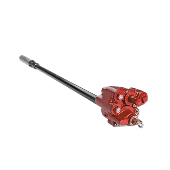
Catalog detail to verify: the original record contains both 1.5 HP and 1 HP. Neither is confirmed for this SKU; we will check the nameplate before quoting.
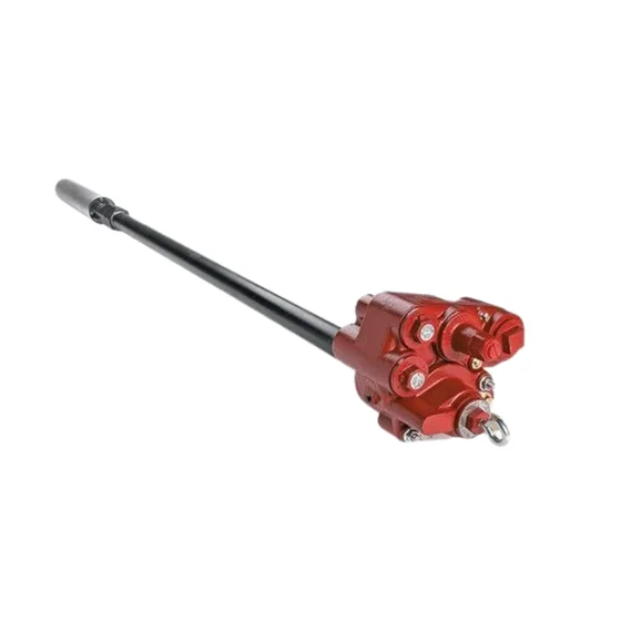
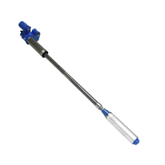
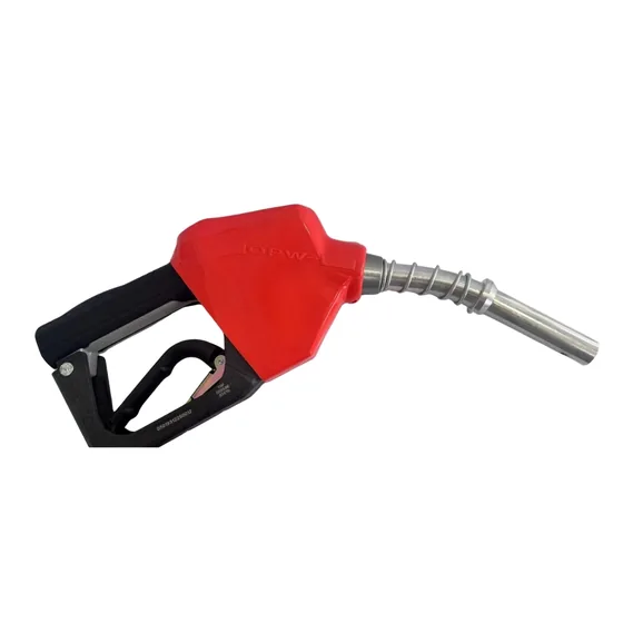
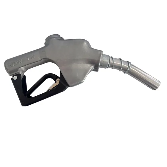
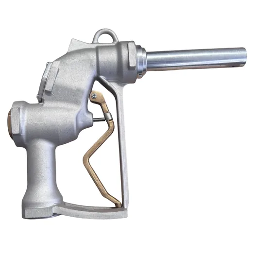
Compare the models and add the nozzle you need to your inquiry. If you have questions about the connections, tell us so we can help review them.
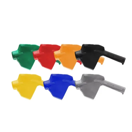
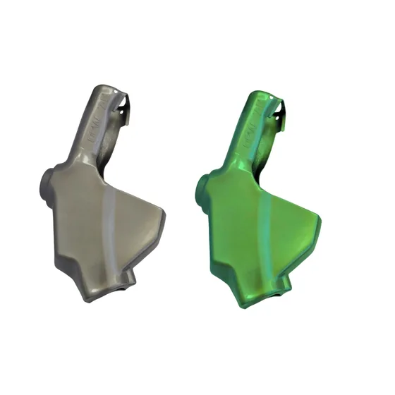
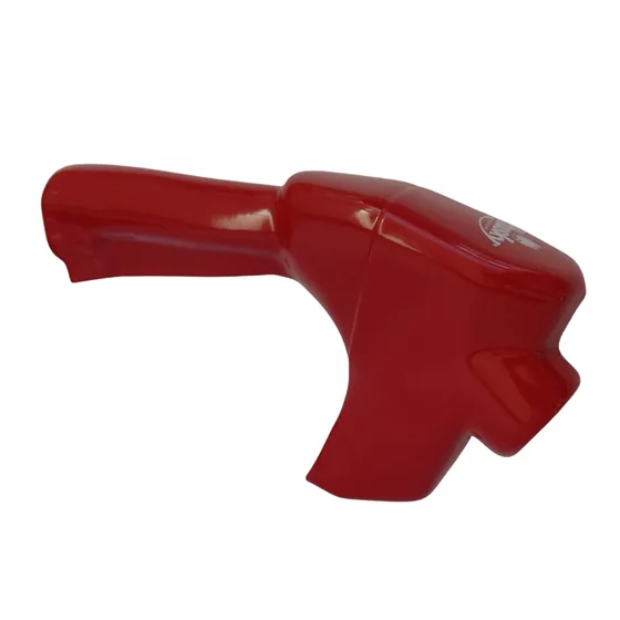
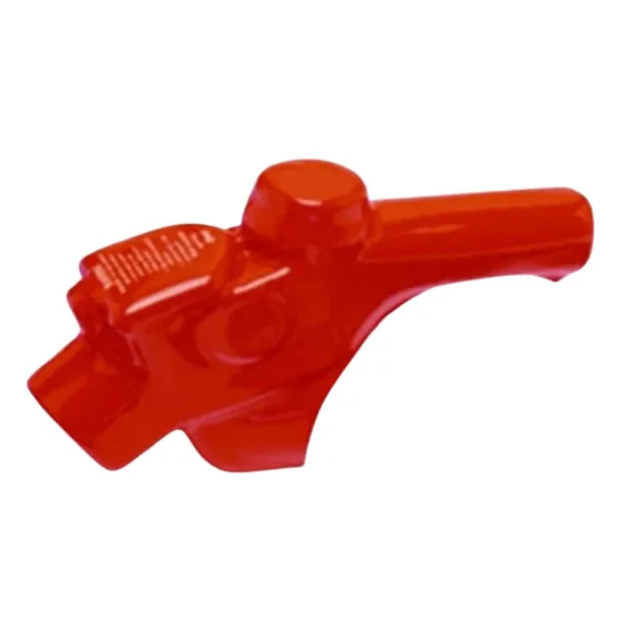
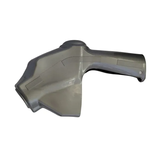
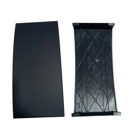
Covers for the dispensing nozzle. Match the nozzle make and model as well as the size; color does not determine fuel compatibility.
Share the nozzle make, model and a photo. Inlet size alone does not confirm that a cover will fit.
Choose a reference by size and length. You can also include the short breakaway hose.
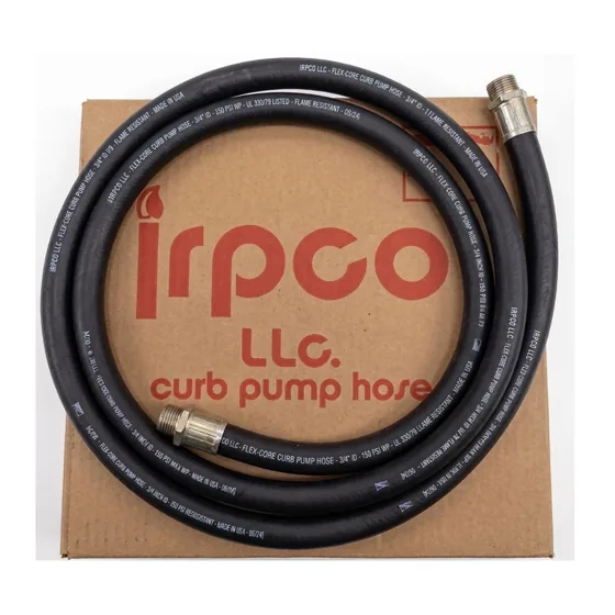
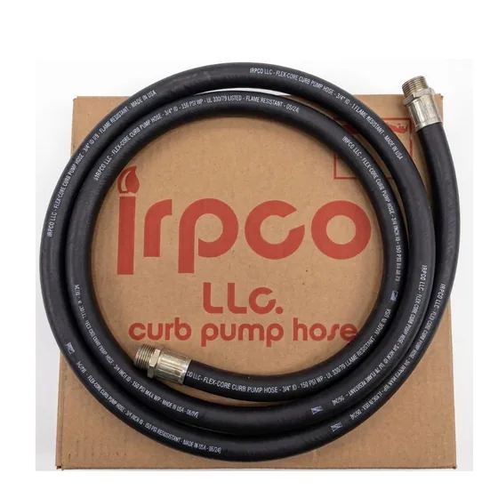
Catalog detail to verify: the title says 3/4 in × 14 ft, while the description confirms only 3/4 in. We will confirm the length and brand before quoting.
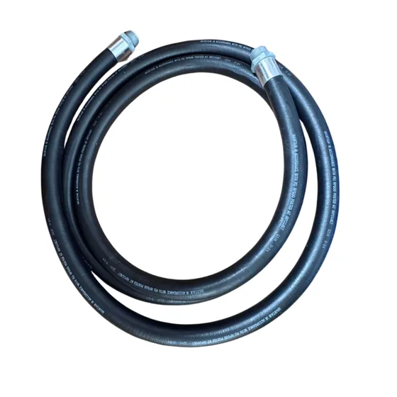
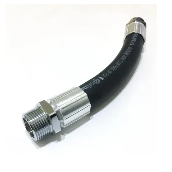
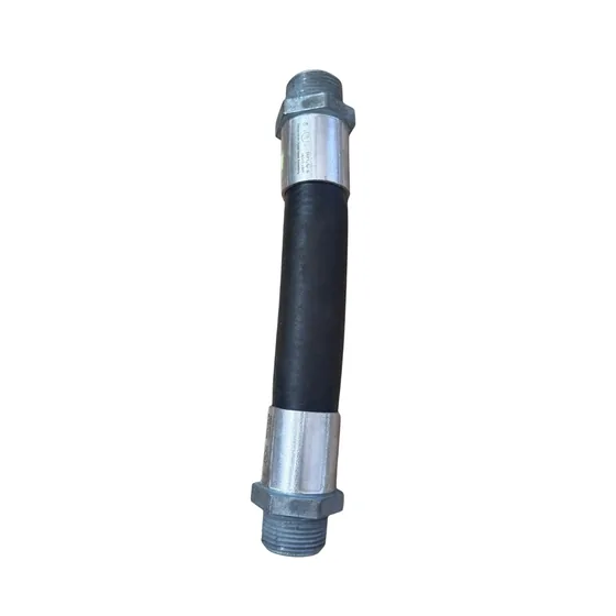
Explore the models and add the size or reference you need to your inquiry.
Specify the model, connections and fuel. The cover is quoted separately; it is not a breakaway valve. Check the short hose and its length against the manufacturer requirements.
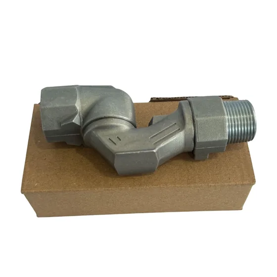
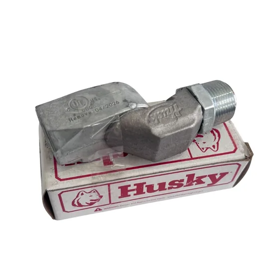
Swivel connections listed in the catalog, with different configurations to review.
Explore the catalog references. If you are unsure which one you need, tell us about your equipment or fuel and we can help find it.
Share the installed filter code, fuel type, micron rating, thread and flow rate. Select the cartridge for its filter head; the listed filters are not all interchangeable.
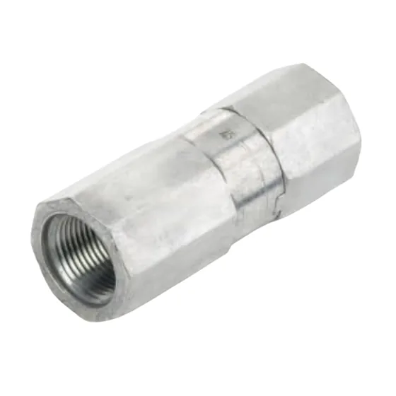
Compare the references and add the valve you need to your inquiry. You can also ask about its replacement fuse.
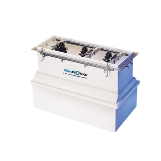
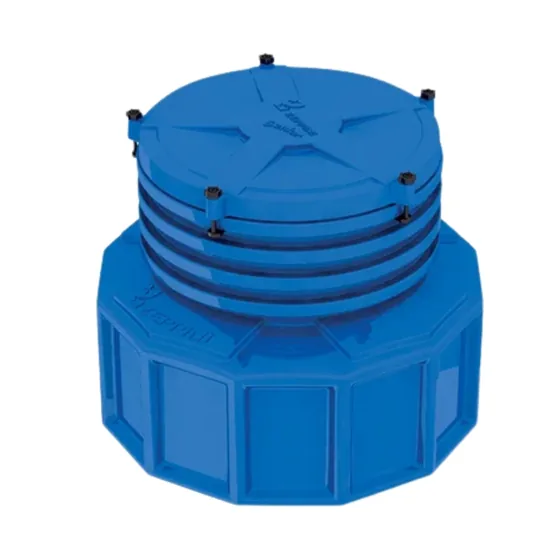
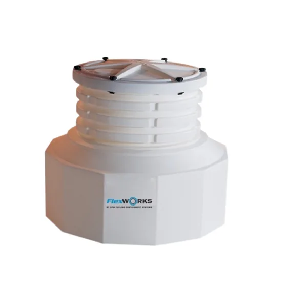
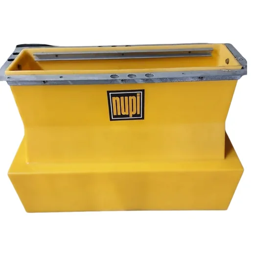
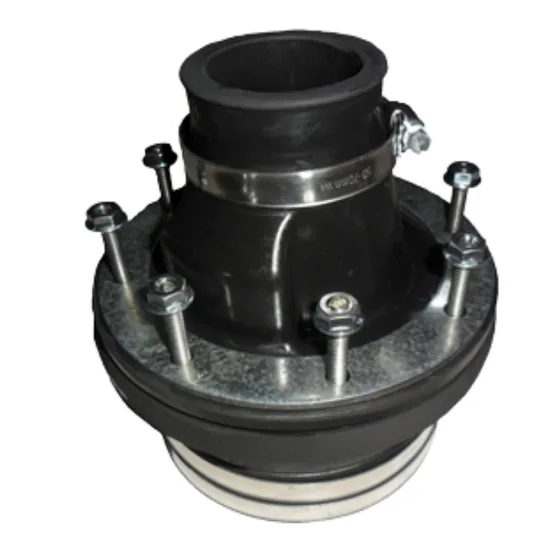
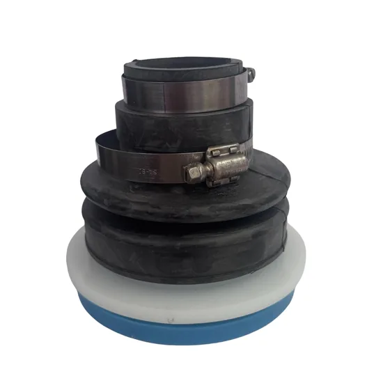
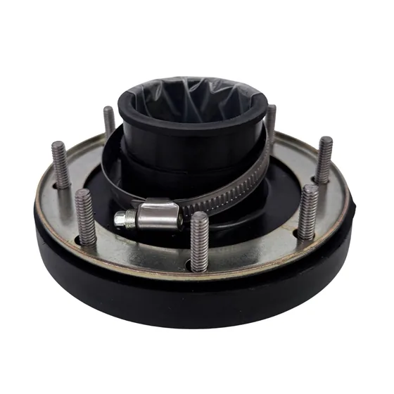
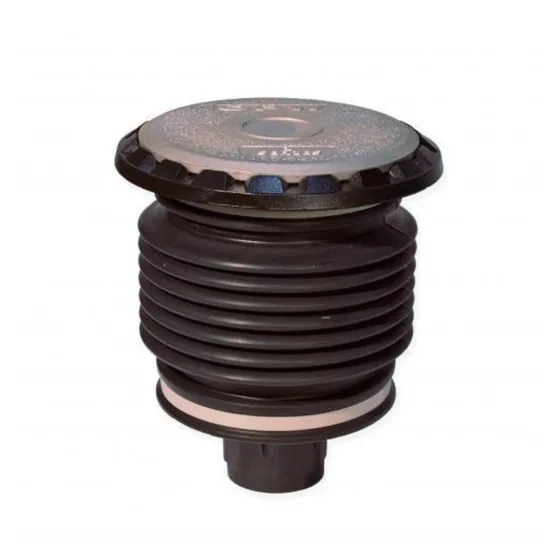
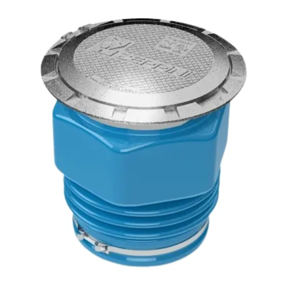
Explore tank and dispenser sumps and entry boots. Include approximate project dimensions in your inquiry.
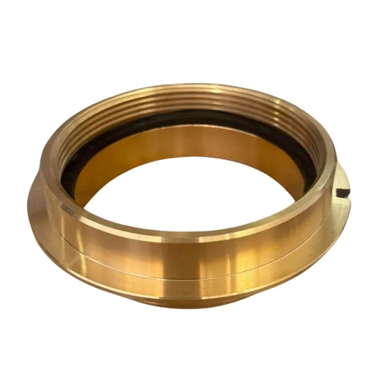
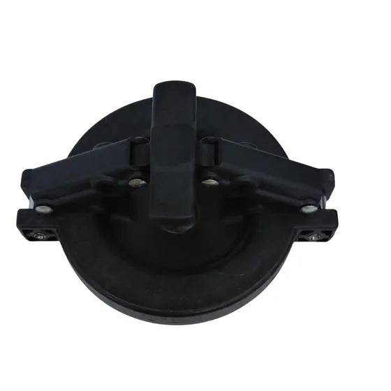
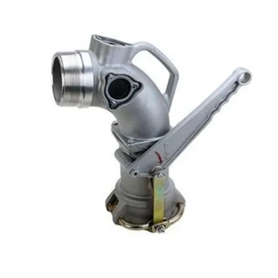
Fill caps, adapters, and spill containers for the tank filling area. Add the references you need to your inquiry and we can help review them.
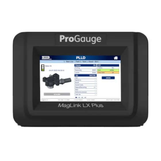
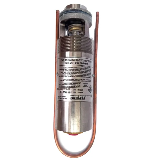
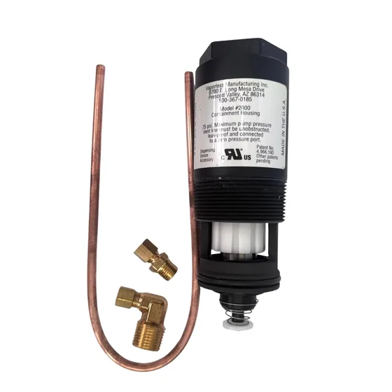
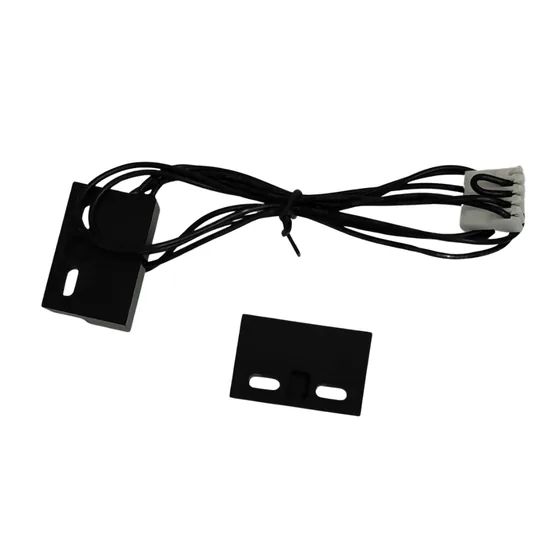
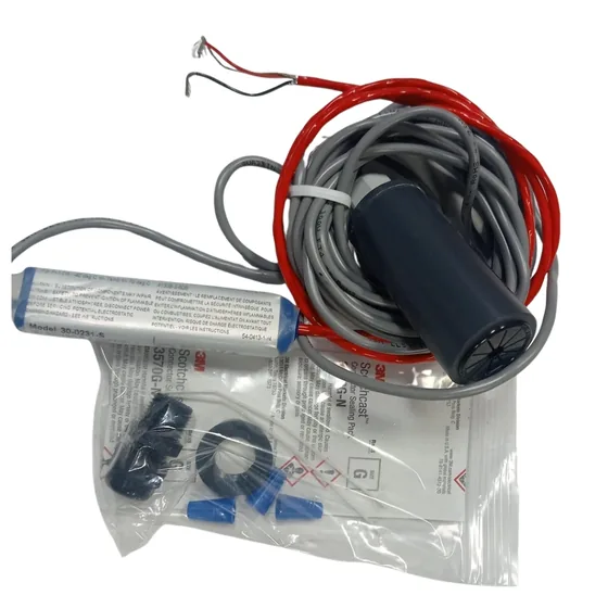
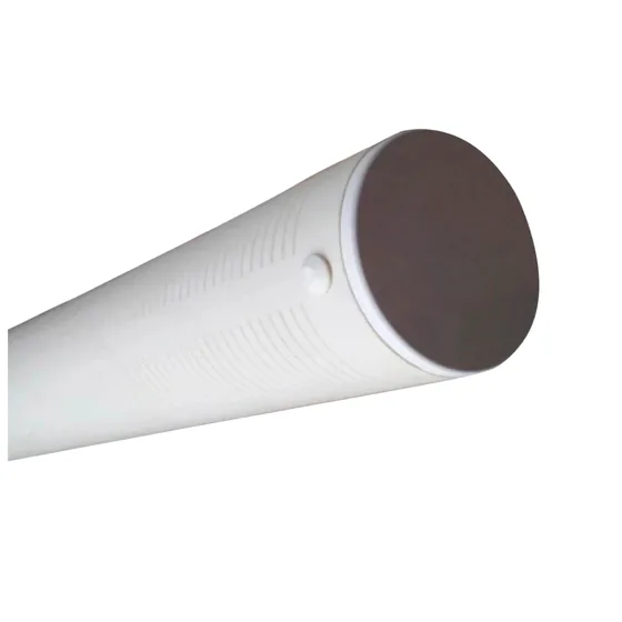
Explore consoles, detectors, sensors, and monitoring tubes. If you are unsure which part you need, tell us about your system and we can help.
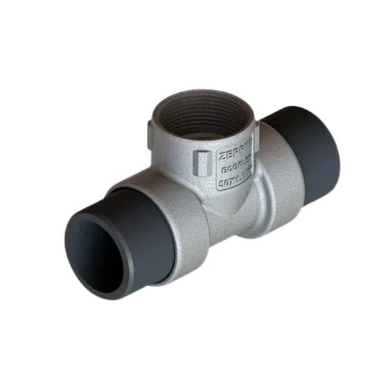
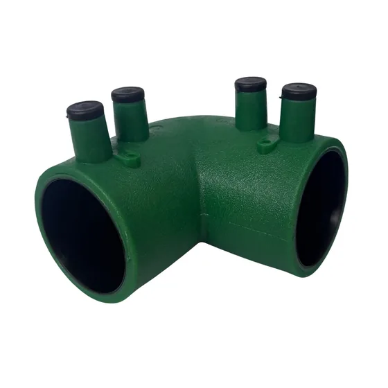
Explore catalog piping and fittings. Include the size and system type in your inquiry so we can help find the right references.
Catalog detail to verify: the title says 1.5 in, while the description says 1 in. We will confirm the size before quoting.
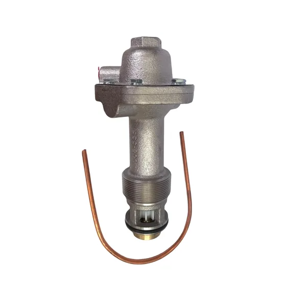
Explore pressure/vacuum vent valves and vent piping. This path is separate from the line supplying fuel to the dispenser.
Specify the tank, product, connection and required model. Pressure/vacuum and float vent valves serve different functions. The illustrated terminal does not identify a model or a pressure setting.
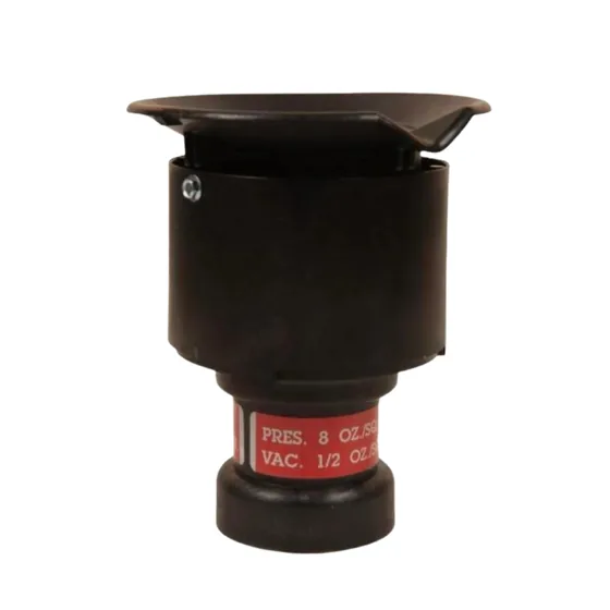
Valve · pressure/vacuum
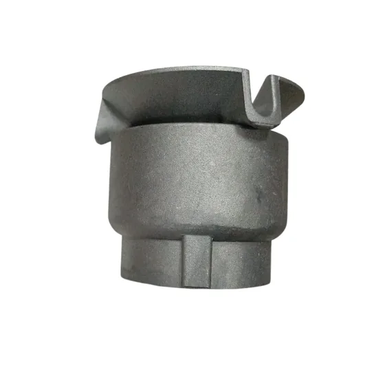
Valve · pressure/vacuum
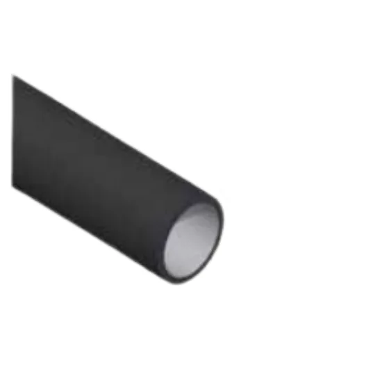
Pipe · vapor venting
Explore Wayne Helix and tell us how many products and dispensing positions you need.
Wayne Helix
Tell us how many fuel products and dispensing positions you need.
Compare catalog control references. To select equipment, we need the pump nameplate, power supply and system configuration. These boxes are not depicted inside the sump.
We need the pump manufacturer, model, power rating, voltage and phases, plus the required control function. A junction box or an Ex box does not replace a controller.
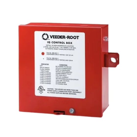
Control box · configuration to verify
The “1 1/2” reference does not confirm power rating or dimensions. We will verify the nameplate, model and power supply before quoting.
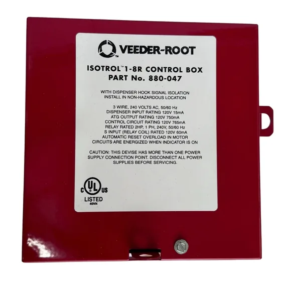
Electronic control · model to verify
The “IS” abbreviation does not establish an electrical classification. We will verify the model and system compatibility before quoting.
Communication cable, flexible conduit, boxes and connectors serve different purposes. Tell us the equipment and intended use of each reference so we can review the selection.
Distinguish power, communication and grounding. Share the equipment, length and project specification. Conduit protects the cable route; it is neither a conductor nor a fuel hose.
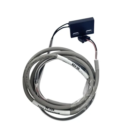
Cable · communication
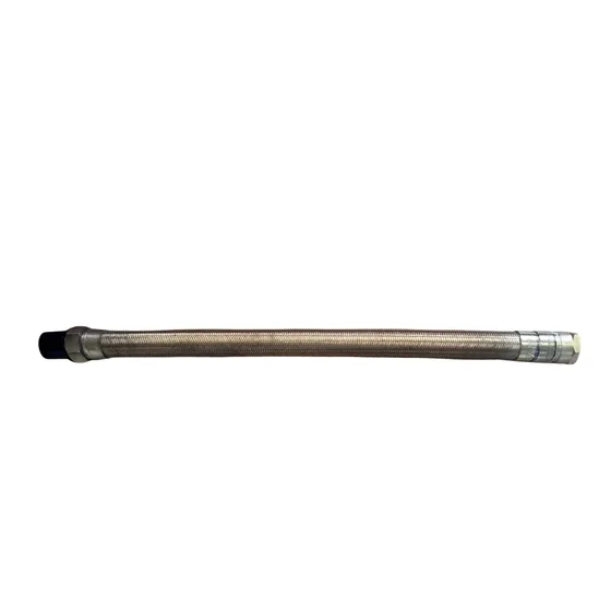
Conduit · electrical routing
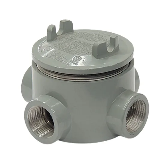
Electrical box · classification to verify
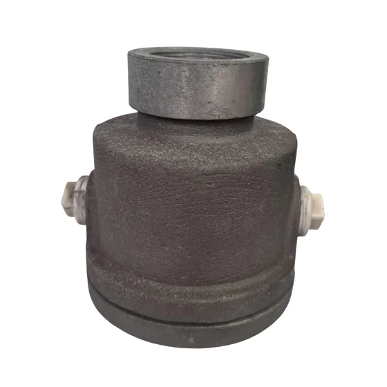
Junction box · sensors
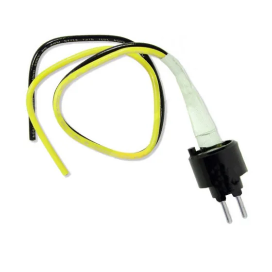
Connection · submersible pump
Catalog details to verify: “RED JACK” does not confirm the Red Jacket brand or compatible equipment. We will verify the brand and model before quoting.
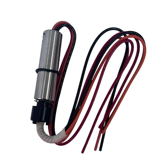
Connection · submersible pump
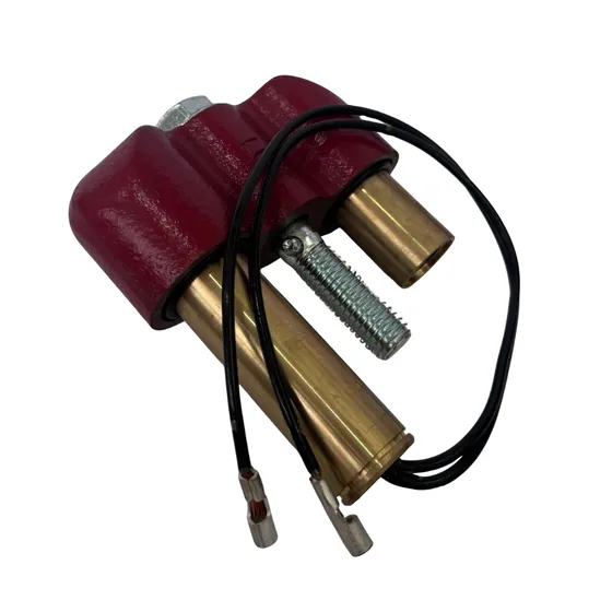
Connection · submersible pump
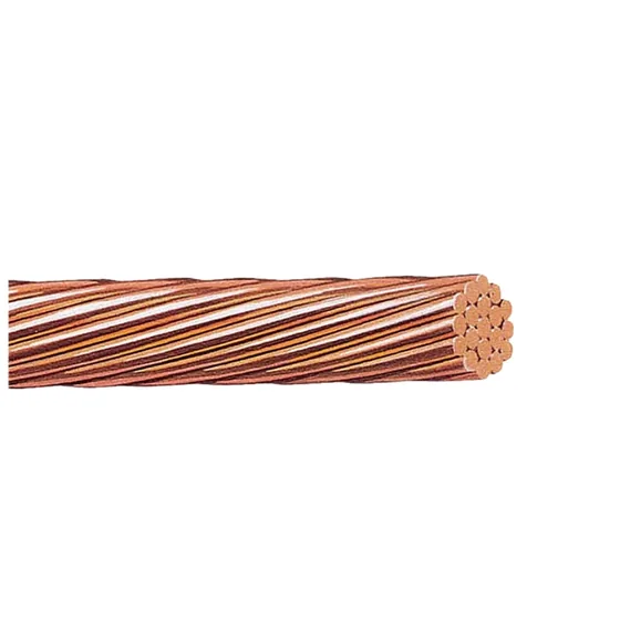
Conductor · grounding
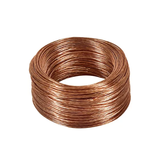
Conductor · grounding
The fill connection and its spill containment are separate from the pump sump. The submersible pump delivers product; a dedicated probe measures the tank, while another sensor can monitor the sump.
For remote filling, a lateral line feeds a separate tank-top fill sump and drop tube. Its route and protection require project design.
OPW mechanical entry boot ↗OPW fill spill containment ↗The conceptual Wayne Helix reference separates user controls from the hydraulic compartment. The shear valve is structurally secured; filters, metering, hoses, breakaway, swivel and nozzle vary by equipment configuration.
Wayne Helix family ↗OPW shear valve ↗Catalog filters ↗OPW 11AP nozzle ↗The delivery path is outlet → short hose → breakaway → main hose → swivel → nozzle. Product and connections vary by configuration.
IRPCO main hose ↗Breakaway hose section ↗OPW 68EZR breakaway ↗OPW 241TPS swivel ↗