From the station to each component
Explore our 3D interactive fuel station, inspect the submersible pump and Wayne Helix dispenser, or prepare a request in the station lab. If you already know what you need, go straight to the store.

Selection and technical context
In this article
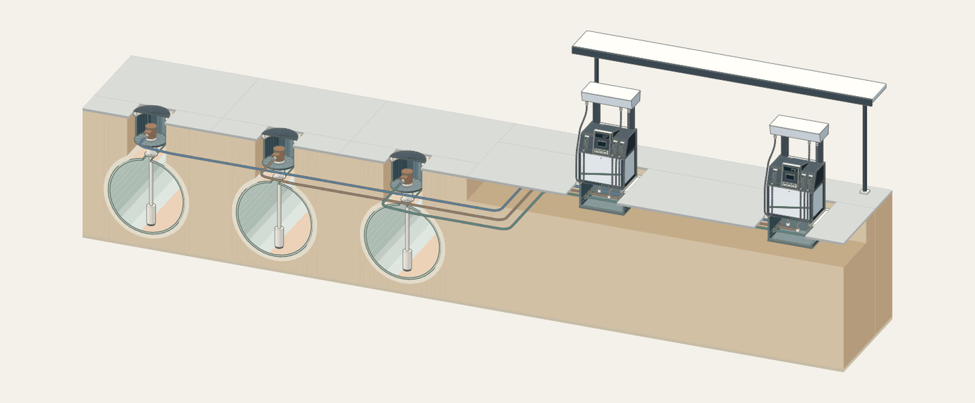
At a fuel station, underground tanks, submersible pumps, product lines and dispensers work as a single connected system. We created an interactive station so you can tour those assemblies, see how they relate and take a closer look at the components and catalog references used in our daily work.
If you already know the product or its code, you can go straight to the store, find it and add it to a quote. If you first want to understand what each assembly does across the station, begin with the overview and open the equipment that interests you. The visual walkthrough is optional; you do not have to complete it to request a quote.
Start with the system and the underground tank
The overview arranges the station into three independent product circuits running from underground storage to the dispensing island. You can focus on tanks, product lines or dispensing equipment, or start an optional one-minute guided tour to follow the fuel path from the tank to the nozzle.
Opening the tank cross-section separates the fill connection (with its spill container and drop tube), gauging probe, vent line and the tank sump surrounding the pump head. From there, you can launch the 3D submersible pump explorer—based on a conceptual visual study of the Red Jacket STP platform—and switch between Assembled, Cutaway and Exploded views to separate 24 parts across the manifold head, packer, column pipe, submerged motor-pump unit (UMP), tank sump and sealed entry boot.
Both the schematic and the 3D viewer are conceptual and not to scale. They illustrate how penetrations and secondary containment relate; they are not an installation design, construction drawing or rating specification for a particular unit.
Take a closer look at the dispenser and its parts
You can also jump directly to the Wayne Helix 5000 explorer. Start with its photograph, then select “Explore in 3D” to rotate and enlarge the model. In the Helix viewer you can switch between Assembled, Cutaway and Exploded modes (with 0–100% adjustable separation) to inspect 18 educational assemblies: the dispenser containment sump, entry boots, emergency shear valves anchored at island level, filters, metering and flow control, and the separation between upper electronics and the lower hydraulic cabinet, referencing the Wayne Helix 4000/5000 family.
Selecting an external hanging-hardware component—nozzle, main hose, whip hose, swivel or breakaway—displays its photograph and a representative reference from our catalog (such as OPW 11AP nozzles, OPW 241TPS swivels, OPW 68EZR reconnectable breakaways or IRPCO hoses). The nozzle cover is explored separately and lets you note a preferred color, which remains subject to confirmation based on nozzle model and availability.
The experience pairs illustrative 3D models with photos and listings for real catalog products. The 3D geometry is not a CAD file or manufacturing drawing, and the example parts do not automatically form a pre-verified kit. Before quoting, our team confirms the version, threads, fuel type, flow rate and compatibility for your equipment.
From the model to your request: station lab or store
When you want to prepare a request with equipment context, the Station lab brings together 28 educational components and 48 curated references across three workflows: understanding the system, parts and maintenance, or planning a project. It lets you build a draft with the parts and notes you reviewed, identify your station or equipment, and send the inquiry to our team.
The store remains the fastest route when you already know the required part or SKU: open a category or listing, review its details and request a quote directly. And if you want to review family documentation and commercial options, visit the Wayne Helix page or the Dispensers guide in Master University.