Skip to content

March 24, 2026

Underground fuel tank installation guide (PEI RP100)

Ing. Armando E. Campos

By Ing. Armando E. Campos

Engineer

Underground fuel tank installation guide (PEI RP100)

Installing an underground fuel tank is not just another civil works job. It is an intervention on an asset that will remain buried, out of sight, for 25 to 30 years, holding a flammable liquid above an aquifer the city depends on. When an installation fails, it almost never fails because of the tank: it fails because of poorly compacted backfill, anchoring calculated for the wrong depth, cathodic protection connected without electrical continuity, a spill bucket installed with the wrong slope. Those errors are not visible on handover day. They show up three or five years later, in an interstitial leak or in a tank deflection the manufacturer never approved.

The technical framework governing installation in the U.S. market — and which we apply as a reference in Panama, where tightness-test safety is governed by the Fire Department (NFPA 30/30A), the environmental side by MIAMBIENTE, and the SNE oversees the hydrocarbons sector — is PEI RP100-17, *Recommended Practices for Installation of Underground Liquid Storage Systems*, published by the Petroleum Equipment Institute. This guide walks through the installation following the flow of RP100: from the written plan to the final handover document. The figures we cite (test pressure, backfill depths, lifting angle) come from the text of RP100-17; the specific numbers of current Panamanian resolutions are re-verified at the time of a concrete intervention, not generalized here.

If you are going to install a tank at your station, what follows is the correct order of decisions, and the errors that cost the most when reversed. If you want us to review the specific project, request a station assessment.

Before the job: the written plan and site conditions

RP100-17 starts where many projects start badly: in planning. Per PEI RP100-17 §1.7, the written plan must describe the property, identify tank size and location, indicate the liquids to be stored, locate dispensers and piping, and specify construction materials, piping dimensions, electrical service location, and vent dimensions, observation wells, vapor recovery, and metering or monitoring systems. If the design includes a hold-down pad or other anchoring devices, their dimensions and construction details also go in the plan; the same for the location of the cathodic protection components.

That level of detail is not formalism. The written plan is what allows installers to work with precise guidance instead of improvising in the face of real conditions. And §1.7 is direct: selecting equipment and materials compatible with each other and with the fluids is necessary to ensure the long-term integrity of the system. With E10 blends that sentence carries weight: there are elastomers that ethanol degrades, and if the selection of gaskets and flex connectors was not made with the real fluid in mind, the plan was born lame.

RP100 also warns, in §1.8, that even a well-made plan may require revision during the job: a higher-than-expected water table can force anchoring the tanks, or an apparently sound tank can reveal deterioration when excavated and make replacement advisable. The competent installer anticipates, detects, and adapts. §1.6 underscores it: the greatest protection against storage-system failure and liability exposure is the use of installers with the experience and integrity to insist on doing the work correctly.

In §1.9, RP100 notes that corrosion of certain metals exposed to diesel or ethanol-blended fuels has become problematic across all types of UST systems in recent years. And in §1.10 it recalls the hard rule of compliance: consult the authorities having jurisdiction (in Panama, SNE and MIAMBIENTE; the Fire Department for safety) before finalizing the drawings or starting construction. Specific requirements vary among jurisdictions.

Receiving and handling the tank: lifting, lowering, and storage

Section 2 of RP100 is where most installations are damaged before touching the hole. Per PEI RP100-17 §2.1, although steel tanks and fiberglass-reinforced plastic (FRP) tanks are designed to withstand normal handling, they can be damaged during transport or installation. Tanks must not be dropped, dragged, or handled with sharp objects and, except for minimal movement needed for inspection and testing, must not be rolled. If the tank is damaged, it must be repaired per the manufacturer's instructions.

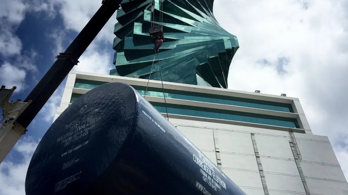
Lifting has a precise geometric rule. Per PEI RP100-17 §2.2, the correct way to move a tank is to lift it using the lifting lugs installed by the manufacturer. When two lugs are used, the angle between the lifting cable and vertical must not exceed 30 degrees; a spreader bar must be used when necessary, and the tank maneuvered with tag lines at each end. If tanks must be relocated within the job site, they must be lifted, not rolled. And before any movement, verify that the lifting equipment has sufficient capacity and reach. RP100's warning is categorical: never place chains or cables around the tank wall.

On-site storage is also governed. PEI RP100-17 §2.3 says to place tanks in a safe area where accidental damage or vandalism is minimized, free of rocks and foreign objects, chocked until the moment of installation and, if strong winds are expected and the tanks could move, tied down with nylon rope at least ½ inch in diameter secured to stakes of suitable size and number. An FRP tank rolling in the wind on a slab breaks against the curb, and that break is the first thing the pre-installation inspection discovers. §2.4 completes the picture: piping and equipment are stored in a safe area, away from excavations, work zones, and walkways, preventing damage that could cause leaks or accelerated corrosion after installation.

Site preparation: excavation, depth, and backfill

Section 4 of RP100 governs excavation. Per PEI RP100-17 §4.1, the excavation must provide adequate space for tanks, piping, and associated equipment, and for the placement and compaction of backfill, particularly under the circumference of the tank body and the ends. The slope of the walls is determined by soil conditions, depth, shoring requirements, and, if workers must enter, safety considerations. The entry of surface water must be prevented by building an earth dike or other means. The warning is explicit: determine the location of overhead and underground utilities before excavating.

The maximum burial depth has its own section, §4.6, because burying a tank too deep can exceed its structural capacity. And the minimum cover depth is governed by §4.4 (traffic areas) and §4.5 (non-traffic areas): insufficient cover under vehicle traffic is a recipe for deflection and failure.

Backfill is where the installation is won or lost. PEI RP100-17 §5.1 enumerates the common deficiencies that affect structural integrity and coatings: use of the wrong backfill material; inadequate or improper placement or compaction; rocks or debris left in the excavation; voids under the lower quadrant of the tank; failure to prevent migration of the backfill material. Any of those five turns a sound tank into a poorly supported one.

The material is also specified. Per PEI RP100-17 §5.4, for steel, composite (fiberglass-clad steel), and jacketed tanks, the backfill must be clean, well-graded, free-flowing, non-corrosive, and inert material (sand, crushed stone, or pea gravel). It must be verified free of debris, rock, ice, snow, or organic material. For fiberglass tanks, §5.6 specifies pea gravel and crushed stone as standard materials, with sand only by manufacturer approval.

Placement has concrete figures. Per PEI RP100-17 §5.5 and §5.7, the bottom of the excavation is covered with properly placed backfill to a depth of at least 1 foot (if a hold-down pad is required, the depth can be reduced to 6 inches). Compaction, per §5.8, is done in lifts of 12 to 18 inches with compaction after each lift, repeating up to a level of at least 60% of the vertical height of the tank. These numbers are not suggestions: they are what supports the tank body and prevents the deflection that §5.9 measures as an indicator of installation quality.

Anchoring and cathodic protection: the two systems you do not improvise

If the water table is high or there is a flood risk, the tank floats. Per PEI RP100-17 §6.1, where installations are in areas with high water tables or flooding, provision must be made so that tanks, full or empty, do not float during a rise in the water level, up to the maximum flood stage established. §6.4 enumerates the supplementary anchoring methods (hold-down pads, deadmen, earth anchors) when sufficient burial depth to counteract buoyancy is not feasible. The buoyancy calculation, warns §6.1, is based on worst-case conditions: water level at finished pavement level and an empty tank.

Cathodic protection is the other system that admits no improvisation. Per PEI RP100-17 §12.1, underground metal storage tanks and product piping systems in contact with the soil must have cathodic protection. Systems built with corrosion-resistant materials (FRP) do not require additional cathodic protection. §6.6 covers electrical isolation, and §6.7 the fastening methods. The operational lesson: cathodic protection installed without electrical continuity between tank, piping, and accessories is nonexistent cathodic protection. Continuity verification is part of the handover.

Secondary containment, spill prevention, and leak detection

RP100 covers spill containment and overfill prevention in its section 7. Per PEI RP100-17 §7.1 and §7.2, spill containment (the spill bucket) captures fuel spilled when connecting and disconnecting the truck hose; overfill prevention cuts off flow when the tank reaches 90-95% of capacity. Both are installed per §7.4 and tested, along with the containment sumps, under PEI RP1200 practices every 3 years.

Secondary containment, section 8, provides an additional layer of protection. Per PEI RP100-17 §8.1, these systems must be installed to contain any release from tanks, piping, or equipment; facilitate the detection of any release; and provide access for the recovery of released product. They include double-walled spill buckets, double-walled tanks, double-walled piping, and containment sumps.

Leak detection, section 9, is the first line of early warning. Per PEI RP100-17 §9.1, the purpose of the system is to detect releases from the tank, piping, and accessories before they reach the environment. For double-walled tanks, interstitial monitoring (manual or electronic, §9.2) is the reference method.

Pre-operation testing: what is signed before covering

RP100 sets explicit tests that must be performed and documented before putting the system into operation. Per PEI RP100-17 §3.2, before installation the factory-installed steel or cast-iron plugs are removed, sealed, and reinstalled; the thread protectors are replaced with liquid-tight steel or cast-iron plugs; and single-wall tanks are pressure-tested with 3 to 5 psig of air, applying soap solution to all surfaces, seams, and fittings while inspecting for bubbles. The warning in §3.2 is severe: air testing above 5 psig (3 psig for 12-foot-diameter FRP tanks) is dangerous and can damage the tank.

Piping has its own protocol. Per PEI RP100-17 §11.1, new product piping is air-tested at 50 psig or the manufacturer's recommended pressure for 1 hour, applying soap solution to joints and surfaces. And §11.1.4 is the final test that closes it: immediately before putting the underground piping into service, a hydrostatic test is conducted at 150% of the operating pressure, but not less than 50 psig. Skipping that test is putting piping into service without certified tightness.

Documentation: what the client must receive at closeout

An installation is compliant when the client receives the documentation that backs each decision. The minimum, aligned with RP100-17:

  • Copy of the signed written plan (§1.7), including material specifications and fluid compatibility.
  • Log of unexpected conditions found and how they were resolved (§1.8).
  • Handling and lifting record, with cable angle verified ≤30° (§2.2).
  • Pre-installation inspection report with photos (§3.1) and the result of the tank air test (§3.2).
  • Backfill calculation record: material, lifts, % compaction, deflection measured vs. manufacturer's limit (§5.8, §5.9).
  • Buoyancy record and, if applicable, anchoring record (§6.1, §6.4).
  • Cathodic protection certificate with electrical continuity verification (§12.1, §6.6).
  • Piping test results: initial air test (§11.1) and hydrostatic test at 150% of operating pressure (§11.1.4).
  • As-built drawings with the final location of tanks, piping, vents, observation wells, and the leak detection system.

That folder is what an SNE or MIAMBIENTE auditor asks to see. And it is what an operator needs, five years later, to reconstruct why cathodic protection was designed with that capacity or why the anchoring has that geometry.

Errors that cost the most

Three errors we see in installations done by third parties that cost more to fix than to prevent.

First, backfill without lift-by-lift compaction. The operator pours the material all at once and trusts that it "settles." It does not settle: it gives way under the weight of the full tank, creates voids in the lower quadrant, and the tank's vertical deflection exceeds the manufacturer's limit. §5.9 is explicit that excessive deflection indicates inadequate support. The repair is full excavation.

Second, anchoring calculated for the wrong depth. If the water table rises and the buoyancy calculation was made with outdated soil data, the tank floats, with piping and dispensers connected. §6.1 orders basing the calculation on worst case: water at pavement level and an empty tank. Recalculating under that assumption costs hours; repairing a floated tank costs weeks.

Third, cathodic protection without electrical continuity. The anodes or the impressed-current bed are installed, but an isolating flange or a non-metallic coupling interrupts the circuit. The system "works" on the console reading but protects nothing. §6.6 (electrical isolation) and §12.1 require the system to be correctly connected. Continuity verification is the difference between real protection and a simulation.

Closing

An underground tank installation is the most expensive and most buried asset of a station. Doing it right the first time costs the same as doing it wrong: the difference is who directs the job and what written plan governs it. If you have an installation project underway, or an existing installation you need to audit against RP100, schedule an assessment with us: the first visit leaves a diagnosis of the compliance status and a prioritized list of what remains to close before it becomes a problem.