Skip to content

Pillar

Tanks and pumps

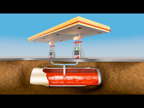
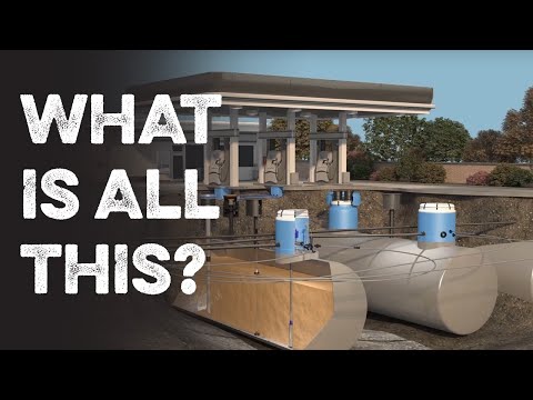
Almost everything that makes a station run is underground: the tank, submersible pump, lines and sumps. Here we explain how those components relate and how to review a calibration chart, always against the design, manufacturer documentation and requirements that apply to the installation.
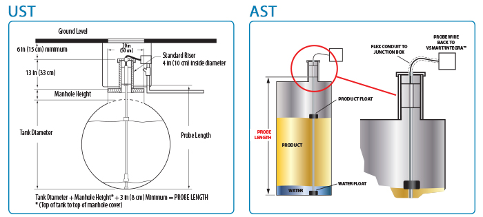
A look at the tank probe

Original OPW 924B diagram: probe configuration in underground and aboveground tanks, with dimensions and floats; original English labels
OPW 924B · Unaltered original diagram. Tap to enlarge.
Details & source

Manufacturer reference for the 924B, with original English labels. Not a universal installation plan or a compatibility statement for other consoles. Check the applicable manual and site design before installation.

Manufacturer documentation

Articles

Recommended videos

External resources. They open on YouTube.

Glossary

STP (submersible turbine pump)
Submersible Turbine Pump. A centrifugal pump inside the tank that pressurizes fuel and pushes it to the dispensers when a customer fuels up.
Sump
A liquid-tight box over the tank or under the dispenser. It contains possible spills and protects the pump-to-pipe connections from the ground.
Drop tube
A vertical pipe inside the tank through which the tanker truck discharges fuel. It houses the valve that stops filling at 95%.
Interstitial space
The gap between the inner and outer wall of a double-walled tank or pipe. Sensors placed there detect a leak before it reaches the ground.

Does your station meet the standard?

Schedule an evaluation with a specialist who knows your station and Panama’s regulations.

Request an evaluation
Conceptual engraving of a fuel station
Conceptual illustration
Image details

AI-assisted editorial engraving. Not a photograph of a Master Services project.